HF Antennas

Working from a "portable" location means that an antenna has to be erected afresh every time, which encourages experimentation with different types on antenna. Below are some the antennas I've put up in the last few months.

MFJ-1792 Dual Band Vertical

I purchased this second hand from a local amateur who claimed he wasn't (yet) old enough to use 80m :-) I should say that from the start I knew this was not designed for portable use. It is made from multiple aluminium tubes and sleeves that have to be bolted together to make the 32ft mast. The resulting "pole" is quite flexible and both sets of guy ropes are definitely needed.

I bought it mostly for the "Top Hat" arrangement that goes on the top of the pole. The 32ft section itself is resonant on ~7Mhz, and the top loading coil and capacitance hat produce an additional resonance on 3.5Mhz. However the use of the loading coil and hat produce a much narrower range of usable frequencies on 80m compared to 40m. This means you have to choose which part of the 80m band you want to use and the "spokes" of the capacity hat have to be trimmed to adjust the resonance to the required frequency. This picture shows the spokes that had been trimmed by the original owner. When I erected the antenna with these fitted I found the 80m resonance was on 3.500Mhz, which was just a little bit too low as I prefer to operate around 3.550Mhz. However it was producing <1.3:1 SWR on both bands.

However for me the biggest draw backs to this antenna were that it took a long time to assemble and it took three of us to put it up and take it down. On the day we put it up I didn't actually manage to work anyone on 80m as I had to pack up before the band started to open in the evening.

80m Vertical

To address the practical problems with the MFJ-1792 I decided to try mounting the "top hat" assembly on an easier to erect pole. Many years ago I purchased an ex-military 27ft telescopic mast, and at the time used it to support a variety of wire antennas. Despite the official instructions saying four soldiers were needed to put it up, I knew I could do it by myself as long as I used the supplied mounting spike which would hold the mast in place while the first set of guy ropes were being adjusted.

However the top of this mast would not directly support the top hat.

A friend on mine turned up this adapter which fits inside the coil former tube.

The adapter allows the loading coil and top had top be placed at the top to the mast.

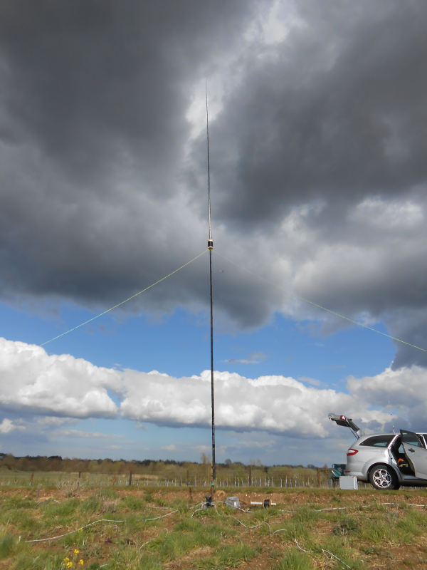
This mast is much more "substantial" than the original aluminium tubing, but it is a LOT heavier! Also with no sideways loads it is quite stable with just one set of guy ropes attached.

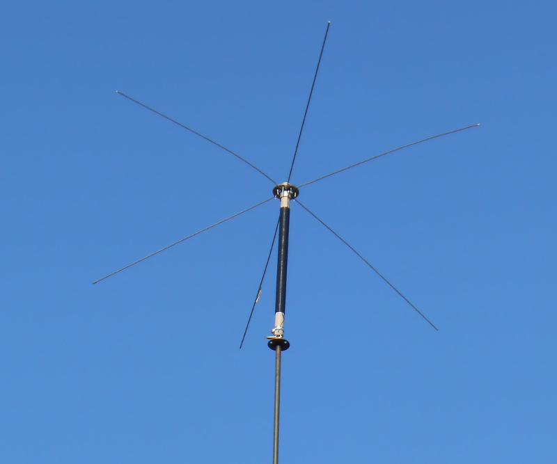
Because this mast is a few feet shorter that the original pole I expected the resonance to have moved away from 3.500Mhz, and with the orginally trimmed spokes fitted it had moved up to 3.660Mhz. I had planned ahead and taken some 1m lengths of aluminium rod with me, so after a few rounds of "Fit hat to mast, push up the mast, measure the resonant frequency, let the mast down, remove hat from mast, trim a few inches of the spokes" I ended up with it resonant at 3.530Mhz.

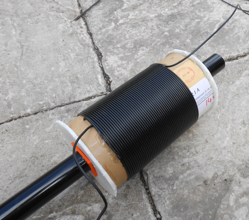
Since the mast itself is shorter I didn't expected the previous good match on 40m. The mast itself is resonant at ~9Mhz, so maybe a small series inductance at the feed point can be used to restore the 40m performance without upsetting the 80m tuning too much. This will be an experiment for next time I put it up.

HF mobile verticals

Follow this link to read about my experiments with "black stick" HF mobile antennas.

A portable topband vertical

My local club has started trying a weekly net on 160m a.k.a Topband. Having had some success of late with various mobile verticals I decided to try and build something that could be used /P to get on the net.

A bit of Googling led me to a design by G3SZU 160m Elevated Fibreglass Vertical Antenna

The design calls for a 176uH loading coil to be placed in the center of a 10m vertical. I looked around for something to use as a former for such a coil and came up with a length of cardboard tube that once upon a time had been used to send a poster through the post. I used this online Coil Inductance Calculator to work out the number of turns on an 11cm diameter former. The ends of the coils were made using a foam "pizza base" held in place with hot glue. I actually wound a couple of turns less that calculated and fixed them in place with hot glue. I wound less as it would be easier to add turns rather than take them off once they were glued in place.

You can just see the orange guy rope plate that holds the coil in place.

While still at home I extended the top sections of the fishing rod and wound on the specified length of wire. This actually formed a reasonable coil when the rod was retracted and made for a quick erection once on site.

I used my normal "bit of angle iron", length of wood and bungees to mount the rod and it was quickly ready to try. A couple of guys were attached as there was a gentle wind and I really didn't want it to fall down across the road !

You can see in the picture some of the radials I put out. I used my 10m long radials in pairs, so in total I laid 7 x 20m long wires. Due to the position next to a road I had to lay them out all to one side of the antenna. This arrangement was easier to deploy than the elevated and tuned counter poises used in the original design. I don't know how this affected the antenna performance, maybe at some time I will try elevated and resonated counterpoises.

More by luck than judgement the antenna resonated at 1880kHz but the SWR dip only came down to 1.7:1 I put my SGC-239 at the base and fed it from the car with a short length of coax. The ATU seemed happier tuning it below the resonant frequency than above the resonant frequency.

Luckily I found a local net on 1908kHz (The AM Preservation Society net) any was able to get reports from stations in North Kent and South Essex. Despite only running 10W from my KX3 all reports were S9 plus.