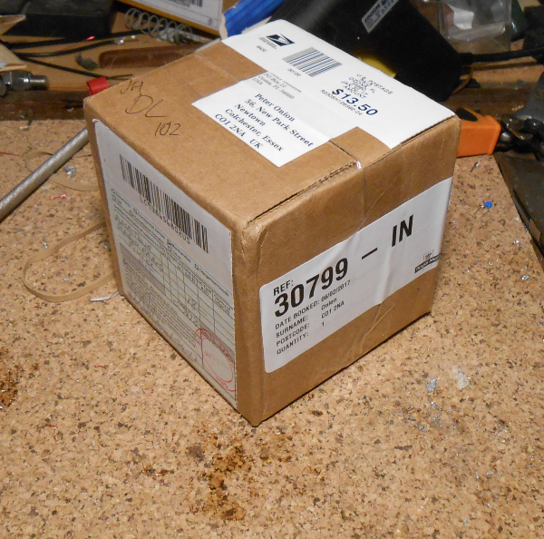
No import tax to pay.
I have been following Martin, G0PJO's build log of the kitsandparts.com "One Watter" qrpp tranceiver kit. After seeing his finished board "in the flesh" at a local meeting I decided to make one for myself. The kit is "universal" in that the same PCB is used regardless for which the band the kit is built.
Two things particularly attracted to this kit
I normally run 10W output on CW on HF, so I decided to also purchase Kitandparts' new 5W P.A. kit at the same time. I will build the One Watter "as is" first and see how it performs, but my plan is to combine the two kits to make a 5W tranceiver. I asked W8DIZ at kitsandparts if anyone had done this already, but it seems the 5W P.A. kit is quite new and he didn't know if it has been done already. There is a bit of experimentation to do concerning weather to use the input attenuator , the pre-amp stage and the One Watter's own P.A. stage.
The two kits came is a small cube shaped box, which unfortunately would not fit through my letter box so I had to go to the local sorting office to collect it.
No import tax to pay.
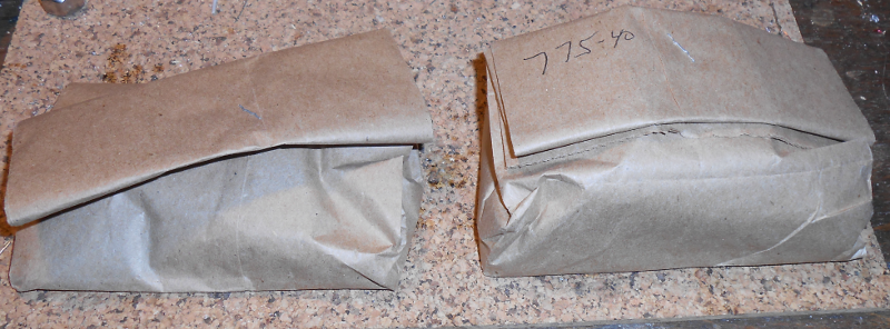
Inside the box were two brown paper bags, one for each kit, and I assume my "One Watter" is serial number 775
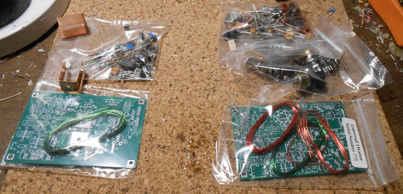
5W PA and One Watter kits.
The One Watter comes in the four plastic bags on the right.
If you follow the instructions on the Kits and parts web site you will follow a "by component type" build order. First you will install all the decoupling capacitors, then resistors, diodes,
IC sockets, capacitors,discrete semiconductors,ICs,inductors and finally the crystals.
I followed these instructions and bar a couple of minor issues it all went together easily.
In most places where components are different depending on which band you are building it is clear what to install, but in a couple of places you have to look through the text
to find the correct component or value to use.
Also, don't be worried that you seem to have components left at the end of the build !
Another "build order" comes in the form of a set of You-Tube videos by K7QO. These take a "block by block" approach which allows some testing to be performed as you go along. He also has a detailed photographic build log but I think this may be for an earlier version of the board so some components might be in slightly different or in different places. If you are new to "kit building" I suggest you at least watch these videos even if you don't follow them when building your board.
I had intended to keep adding to this page as I went along building my board, but once I got started ...... However I did remember to take some pictures along the way, especially to high light a few constructional hints and tips.
Although there are no tiny surface mount components to deal with in the kit, if you have big fingers like me it is still hard to pick up and easy to drop small things like the
capacitors in this kit. Some people like to layout all the components of the bench before they start, but I find this is a recipe for loosing things ! Instead I prefer to keep all the component
in some form of container that is big enough to be able to separate out the component types, but minimises the risk of loosing bits if you drop them.
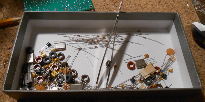
A pair of tweezers are an essential tool for sorting through the components and picking up the one you want. The raised edges
of the box prevent components escaping. In the picture above I have separated out all the resistors ready to install them on the board. These are all 1/8th watt and the colour bands are sometimes
hard to distinguish (especially the green and blue coloured ones) so it is worth taking time to check each resistor's value if you are at all unsure.
I printed out an A3 sized copy of the schematic so that I could cross out the parts as I installed them. Actually I cut the schematic in half and printed each half on A4 and then taped
them together.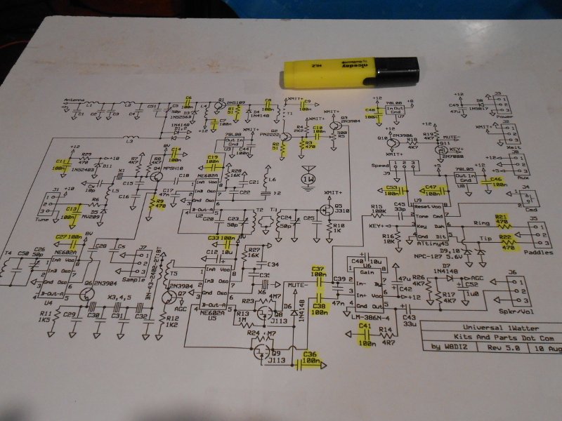
I'm not going to cover things like "how to solder" as there are already plenty of on-line tutorials on such things.
The build is actually quite straight forward, the board is clearly marked and the through plated holes mean that soldering is easy.
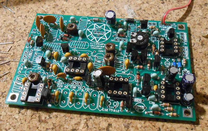
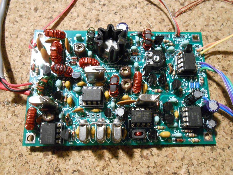
Here is the part built board, just before the installation of the inductors and transformers.
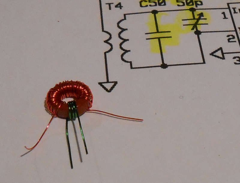
I have been using "magnet wire" for various purposes for many years, and I find it is not necessary to go to the trouble to "strip and tin" the ends of this wire. I have a
professional temperature controlled soldering iron, and with it set to its highest temperature the insulation easily burns off when the iron and solder are applied to make the connection. Here
is T4 ready for insertion into the board.
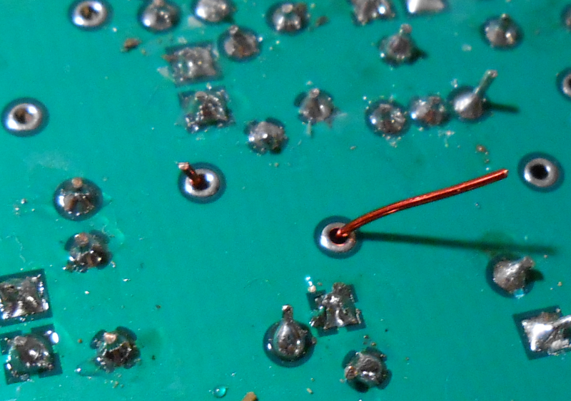
When you cut the ends of the windings, do not cut them all to the same length. If you do, when you present the coil to the board, you will have the difficult task of getting all the wires
into their holes at the same time. If you cut them all to slightly different length, you can insert them one by one. Here is L3 with leads cut to demonstrate the technique.
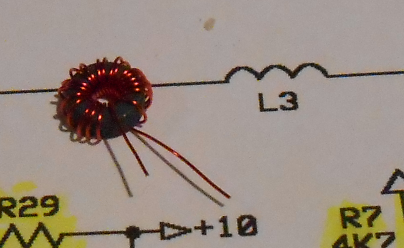
Once the leads are inserted, they can be cut short before soldering, which makes the insulation burn off more easily
as the hot solder can make contact with the uncoated surface of the cut end.
This picture shows the suggested technique to mount the crystals to ensure there is a small gap between their metal can and the board.
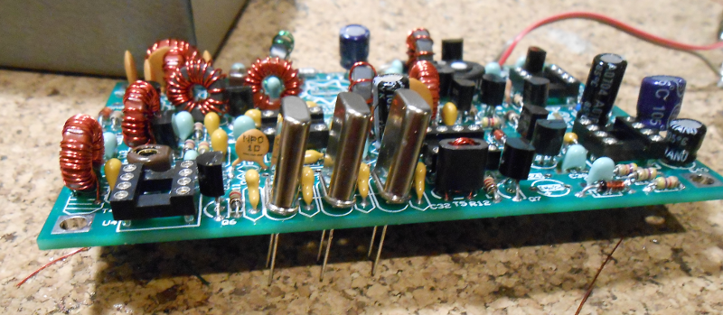
Once soldered in place, they are carefully bent back into a vertical position.
I decided to make direct connections rather then install connectors. Transmitter and receiver alignment was straight forward, peaking C5 and C26 for maximum receive noise,
and peaking C23 and C24 for maximum PA current on transmit and then adjusting R5 for 1W output. On mine this is archived at less then 250mA PA current. (250mA produces nearly 1.5W!)
I chose to install the "Natural Side Tone" resistors R23 and R24 which help to ensure you have correctly
tuned onto another stations signal. I may replace them with lower values as I'm finding the side tone level a bit low.
At my home QTH I don't have the space for a full sized 40M antenna. Instead I have a 6ft diameter home made magnetic loop in the loft. It is not an ideal antenna for using with a QRP rig as its efficiency is probably quite low, but I have had some QSOs using it :-) No great DX of course, but I was pleased to get 559 from the South of France :-)
There are two things I want to do to my 1W40