Multiplex Gemini Build
I collected my Gemini from Galaxy Models on the way
home on a Monday
afternoon. It had it's maiden flight the following
Saturday. Here are a few pictures that I took during the
build. It's not a full "build log" because there wasn't really a
lot to do.
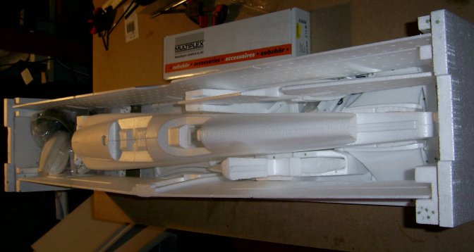 Even the packaging is quite
impressive. I took the time to unpack everything and check it off
against the parts list. Nothing was missing and it helps to know
what every thing is so that you don't start putting the wrong bits
together !
Even the packaging is quite
impressive. I took the time to unpack everything and check it off
against the parts list. Nothing was missing and it helps to know
what every thing is so that you don't start putting the wrong bits
together !
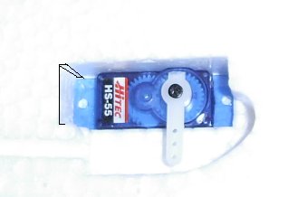
I had purchased four Hitec HS-55s to use in this model. They are
slightly larger than the MPX parts, so the mounting holes in the
fuzelarge needed to me extended backwards by a small amount. The
picture shows where I cut away the foam.
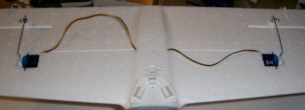
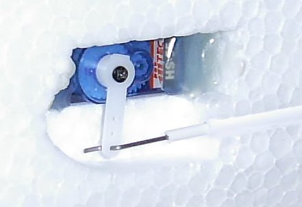 Once the control rods and snakes were
installed the servos were secured in place using hot glue. Using
the outermost hole on the servo arms means the rod lines up
correctly and the throws are about right.
Once the control rods and snakes were
installed the servos were secured in place using hot glue. Using
the outermost hole on the servo arms means the rod lines up
correctly and the throws are about right.
Here's a tip: Don't glue the snakes in too near the ends of the
slot in the fuzelarge as the need to move a little as the servo arm
turns. This is more important at the tail end of the
snakes. Also it reduces the risk of gluing the inner and outer
tubes together, or worse still gluing the rod into the snakes.
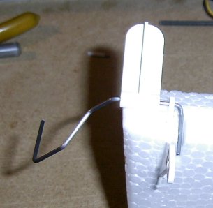
 The manual was not very helpful
when it came to putting the tail wheel assembly together.
The part of the wire sticking up has to
be bent into shape such that it lies in the position of
its shadow in the picture. The manual says to
use "a pair of combination pliers" but I couldn't see how to do this
without putting stress on the plastic parts in the process.
The manual was not very helpful
when it came to putting the tail wheel assembly together.
The part of the wire sticking up has to
be bent into shape such that it lies in the position of
its shadow in the picture. The manual says to
use "a pair of combination pliers" but I couldn't see how to do this
without putting stress on the plastic parts in the process.
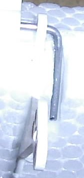
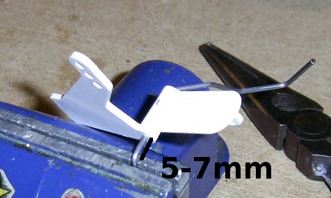 In the end I realised I could put it in
the vice the other way up, and use the 5-7mm of wire that is needed
below the bracket to cover the depth of the vice jaw while bending the
wire to shape.
In the end I realised I could put it in
the vice the other way up, and use the 5-7mm of wire that is needed
below the bracket to cover the depth of the vice jaw while bending the
wire to shape.
 With the hinge and bracket glued in
place I cut a slot for the wire as described in the manual.
With the hinge and bracket glued in
place I cut a slot for the wire as described in the manual.
 In the manual it says "glue the wire into
the rudder using plenty of cyano. Well I tried this, but since
cyano isn't a "space filling" glue it didn't seem very secure to me.
In the manual it says "glue the wire into
the rudder using plenty of cyano. Well I tried this, but since
cyano isn't a "space filling" glue it didn't seem very secure to me.
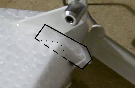 So I cut out a small piece from some
spare foam and glued it in place to fill the rest of the slot.
I've outlined the extra piece in the picture. The excess was
trimmed off after the glue had set.
So I cut out a small piece from some
spare foam and glued it in place to fill the rest of the slot.
I've outlined the extra piece in the picture. The excess was
trimmed off after the glue had set.
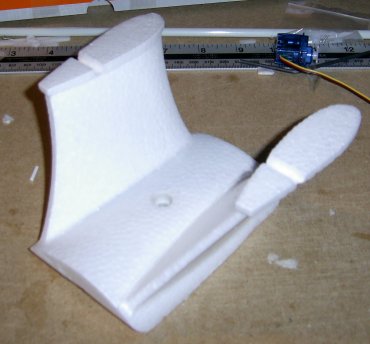 The cabane parts after gluing.
With any of the parts where there is a slot into which another part
fits, don't put glue on the sides as it will "grip" before you
get the parts fully together. Put plenty of glue in the bottom of
the slot so that as the parts come right together it will be forced up
the sides of the joint.
The cabane parts after gluing.
With any of the parts where there is a slot into which another part
fits, don't put glue on the sides as it will "grip" before you
get the parts fully together. Put plenty of glue in the bottom of
the slot so that as the parts come right together it will be forced up
the sides of the joint.
When installing the tail section it is also important to consider which
parts come into contact first and which parts need to slide over each
other before the final position is reached. If you put glue on
these parts it will grip before you get the parts fully together (I
know because this happened to me when putting the elevators into my
Twinstar II. I didn't make the same mistake this time).
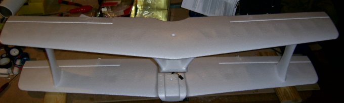
The wings, cabane and wing struts all glued together.
The aileron linkages are quite fiddly to get together. Unlike the
servo mounts in the fuzelarge sides, the aileron mounts did not require
any adjustments.
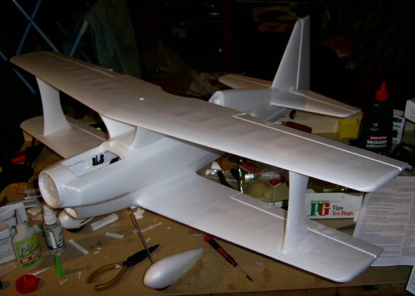
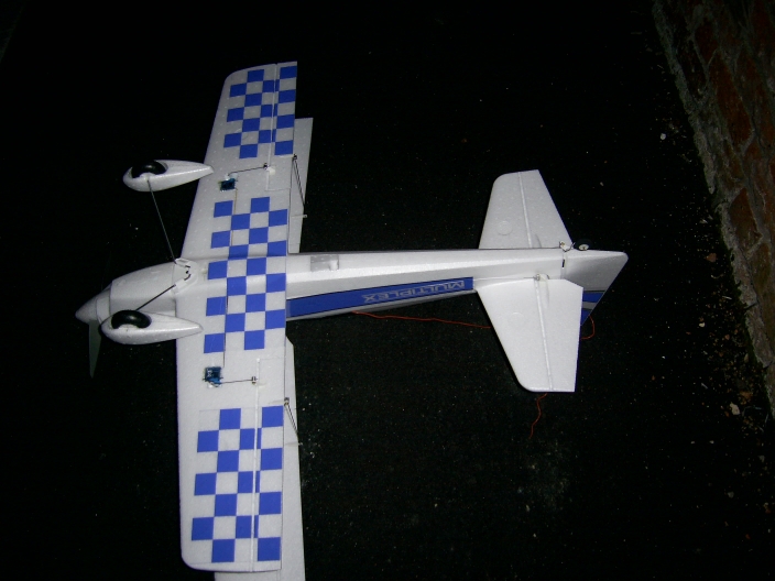
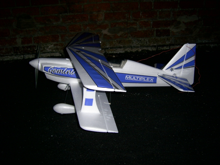
Here it is all put together for the first time.
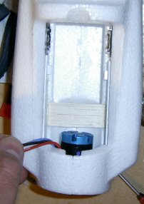 The manual says to install the ESC
behind the motor "suspended on its cables", but I decided to
provide a firm mount to stop it moving about in flight. I cut a
small strip of balsa to size and glued it to the motor mounts in the
sides of the fuzelarge. The ESC is held in place on the mount
with velcro.
The manual says to install the ESC
behind the motor "suspended on its cables", but I decided to
provide a firm mount to stop it moving about in flight. I cut a
small strip of balsa to size and glued it to the motor mounts in the
sides of the fuzelarge. The ESC is held in place on the mount
with velcro.
The final thing to do was to add the transfers. The manual says
this should be done before the major parts are glued together, but I
was
impatient to get it built. The only parts that would be difficult
to do are the inner surfaces of the wings, so mine have remained
undecorated.
So, by the following Saturday it was all ready to go. The last
thing to do was to set up the servo throws and exponentials on my
transmitter. I set these all to the values in the manual.
With a Thunder Power Prolite TP-2100 pack fitted, and a ferrite ring on
the ESC lead, and the Futaba receiver fitted on the top of the
lower wing, the CofG came out 20mm behind the spar in the top
wing. The manual suggests 75mm back from the "nose" of the
top wing which would be on the spar, so mine is a little bit to the
rear of that point.
Post maiden flight
adjustments
The maiden flight was a little bit stressful because I
seemed to have
set the elevator linkage with the servo NOT in it's neutral
position. As a result it need all the nose down trim my
transmitter had and a bit more besides. But I got it round a
couple of circuits and managed a reasonable landing.
So post flight I reset the linkage and reset the transmitter
trim. On the second flight it became obvious that some down
thrust was needed on the motor mount. The design of the mount
makes this adjustment very easy. 1) Remove spinner and prop. 2)
loosen of the middle bolts on each side. 3) Turn top bolts on
each side in one turn and the bottom bolts out half a turn. 4)
Tighten the middle bolts and refit the prop and spinner.
The third flight was much better but it was still climbing when the
throttle was opened, so a further half turn in was added to the top
motor mount bolts.
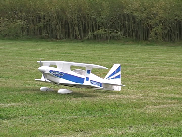
By now I was confident enough to ask someone to use my camera to
get
some video
of the Gemini in action
.