I have been developing a Raspberry Pi based Panadapter for use with my Elecraft KX3 tranciever since the gpu accelerated Fast Fourier Transform libraries were released by the Raspberry Pi Foundation. There have been a couple of problems I've encountered along the way.
First off, when the FFT code was first released I don't think anyone had tested it while there was openGL ES code running the gpu. This proved to be only a temporary set back because Andrew Holme quickly fixed the problems and released a new version of his code
Since the PI does not have any on board audio recording functions I had to use an external USB sound card to capture the I and Q signals from the radio. At that time the USB drivers were still rather flakey, and they could not sustain recording at the rate I required. However this situation has also improved and now it is possible to sample audio at 96kHz with no data loss.
I always considered that using a USB sound card just for recording to be overkill for my application. An alternative provided by the PI is to use the I2S interface provided on the BCM2835 which is a the heart of the PI. However when I investigated the I2S support in the kernel I found it to be very limited. There was some support for I2S DACs but no support for I2S ADCs (except through custom built kernels patched for specific hardware such as the Wolfson Audio card). But over recent months support has improved and some example code was recently published on the PI forums.
When I started the project I had looked around for suitable I2S codecs and found that Sparkfun produce a breakout board for the PCM1803A codec. The data sheet describes like this:
The PCM1803A is high-performance, low-cost,
single-chip stereo analog-to-digital converter with
single-ended analog voltage input. The PCM1803A
uses a delta-sigma modulator with 64- and 128-times
oversampling, and includes a digital decimation filter
and high-pass filter, which removes the dc
component of the input signal. For various
applications, the PCM1803A supports master and
slave modes and four data formats in serial interface.
The PCM1803A is suitable for a wide variety of
cost-sensitive consumer applications where good
performance and operation from a 5-V analog supply
and 3.3-V digital supply are required. The
PCM1803A is fabricated using a highly advanced
CMOS process and is available in a small 20-pin
SSOP package.
So I bought one, only then did I discover the poor state of I2S support, so it has remained unused for a few months.
The example code mentioned above contains code for a simple recording device together with detailed step by step instructions on how to build a loadable kernel module that adds the device to a running kernel and removes the need for a customised kernel to be built.
When the module was loaded a new ALSA recording device became available (listed as "card 2" in the alsacap output shown below) and I used my 'scope to look at the I2S interface signals on the GPIO connector. The bit clock and frame clock were toggling at the frequencies I expected so the next step was to mount and wire up the breakout board.
pi@PiBP ~/alsacap $ ./alsacap -R
*** Scanning for recording devices ***
Card 0, ID `ALSA', name `bcm2835 ALSA'
Card 1, ID `Device', name `USB Audio Device'
  Device 2, ID `USB Audio', name `USB Audio #2', 1 subdevices (1 available)
    2 channels, sampling rate 44100..96000 Hz
    Sample formats: S16_LE, S24_3LE
      Subdevice 0, name `subdevice #0'
Card 2, ID `sndrpisimplecar', name `snd_rpi_simple_card'
  Device 0, ID `simple-card_codec_link dmic-hifi-0', name `', 1 subdevices (1 available)
    2 channels, sampling rate 8000..192000 Hz
    Sample formats: S16_LE, S24_LE, S32_LE
      Subdevice 0, name `subdevice #0'
I now need to customise the module code a bit as my codec does not support all the sampling formats indicated by the alsacap output.
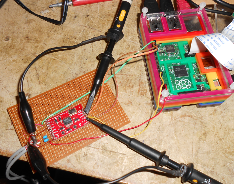
Details of the Sparkfun breakout board can be found on their Web Site. The picture below shows how I mounted their board onto a piece of strip board to make it easier to wire up the required connections.
| Signal | State |
| FMT0 | High |
| FMT1 | Low |
| Mode0 | Low |
| Mode1 | Low |
With the PCM1803A set as a I2S slave, when the ALSA device was opened I could see data on the output pin so I was hopeful it was going to work. But, when I ran my panadapter programme the spectrum displayed was not quite right, with strong signals producing broader traces than I expected. So I modified my programme to dump the samples it was receiving to a file, and when I plotted the data the cause of the poor displays became apparent...
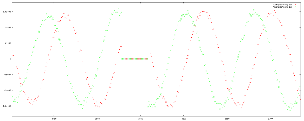
Periodically the PCM1803A was producing a block of zero value samples. The data sheet details how this can happen if the PCM1803A looses synchronisation with the I2S master. I tried changing a few values in the kernel module but they did not fix the problem. While looking at the module code I found that it was straight forward to change the configuration to make the PI the I2S slave.
static struct asoc_simple_card_info snd_rpi_simple_card_info = {
        .card = "snd_rpi_simple_card", // -> snd_soc_card.name
        .name = "simple-card_codec_link", // -> snd_soc_dai_link.name
        .codec = "dmic-codec", // -> snd_soc_dai_link.codec_name
        .platform = "bcm2708-i2s.0", // -> snd_soc_dai_link.platform_name
        .daifmt = 0,
        .cpu_dai = {
                .name = "bcm2708-i2s.0", // -> snd_soc_dai_link.cpu_dai_name
//              .fmt = SND_SOC_DAIFMT_I2S | SND_SOC_DAIFMT_NB_NF | SND_SOC_DAIFMT_CBS_CFS,
                // Change the codec to be I2S master for both clock signals
                .fmt = SND_SOC_DAIFMT_I2S | SND_SOC_DAIFMT_NB_NF | SND_SOC_DAIFMT_CBM_CFM,
                .sysclk = 0 },
        .codec_dai = {
                .name = "dmic-hifi", // -> snd_soc_dai_link.codec_dai_name
                .fmt = 0,
                .sysclk = 0 },
};
To make the PCM1803A the master simply required the two Mode signals to be pulled High.
With the kernel module rebuilt and loaded, and the Mode signals wired to +5V the PI stays sychronised to the PCM1803A.
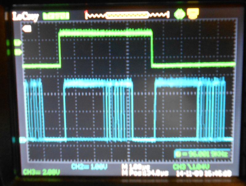
However I did have to change the panadapter code slightly as the 24 bit samples moved from the lower bits to the upper bits of the 32 bit values read from the ALSA device. I think this is a consequence of the frame clock produced by the PCM1803A being 32 bits long where as the frame clock from the PI was only 24bits long. The picture below shows the frame clock in green and the data signal in blue (sorry it's a bit out of focus). You can see how the 24 data bits of each sample come immediately after the edges of the frame clock.
The spectrum graph and waterfall are now displaying correctly. The next step is to mount my Pi B+ and the PCM1803A board into my HDMIPI case but for now it is running on a large LCD monitor.
