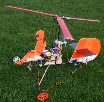

 I added the extra nose wheel in an
attempt to stop it nosing over on the grass, but the high thrust line
and high CofG meant it was never 100% successful. The later
addition of the pre-rotation drive helped but I still had great
difficulty in actually getting the thing to fly.
I added the extra nose wheel in an
attempt to stop it nosing over on the grass, but the high thrust line
and high CofG meant it was never 100% successful. The later
addition of the pre-rotation drive helped but I still had great
difficulty in actually getting the thing to fly. However, it wasn't totally destroyed,
and I had an idea.....
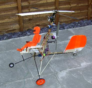
However, it wasn't totally destroyed,
and I had an idea..... |
|
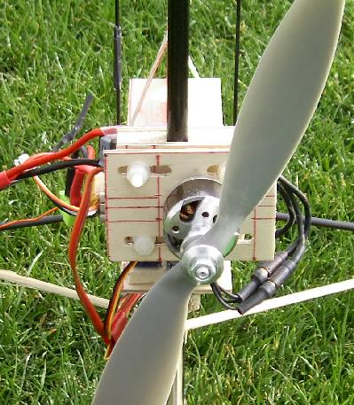 Here's a close up of the motor mount I
built. The slotted plate is angled to the mast with washers, such
that the thrust line is level relative to the horizontal
stabiliser. The slots allowed me to offset the motor to produce
the same result as "side thrust" on a conventional model. The model's
CofG came out just above the arms on the servos, and I set the motor's
vertical position so that the thrust line passed 25mm above the CofG
(Jochen's suggested starting point). The rotor support mast is
clamped between two pieces of ply wood so it's position could be
adjusted by loosening off the bolts. The initial position wasn't
far from correct, but on the first few flights it did tend to pitch up
and down as it flew along. Dropping the motor by 5mm cured that
behaviour.
Here's a close up of the motor mount I
built. The slotted plate is angled to the mast with washers, such
that the thrust line is level relative to the horizontal
stabiliser. The slots allowed me to offset the motor to produce
the same result as "side thrust" on a conventional model. The model's
CofG came out just above the arms on the servos, and I set the motor's
vertical position so that the thrust line passed 25mm above the CofG
(Jochen's suggested starting point). The rotor support mast is
clamped between two pieces of ply wood so it's position could be
adjusted by loosening off the bolts. The initial position wasn't
far from correct, but on the first few flights it did tend to pitch up
and down as it flew along. Dropping the motor by 5mm cured that
behaviour.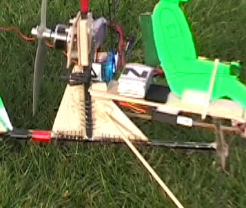 After a few flights (see below)
the epoxy holding the plywood triangles to the boom and mast came
unglued, luckily not while it was airborne ! I took it all apart,
cleared off the old epoxy and added some binding threads. These
have helped to produce a much stronger joint as they helped to keep the
epoxy in the right place while it was setting, and the epoxy flowed
along them to produce a much greater glued area onto the main boom.
After a few flights (see below)
the epoxy holding the plywood triangles to the boom and mast came
unglued, luckily not while it was airborne ! I took it all apart,
cleared off the old epoxy and added some binding threads. These
have helped to produce a much stronger joint as they helped to keep the
epoxy in the right place while it was setting, and the epoxy flowed
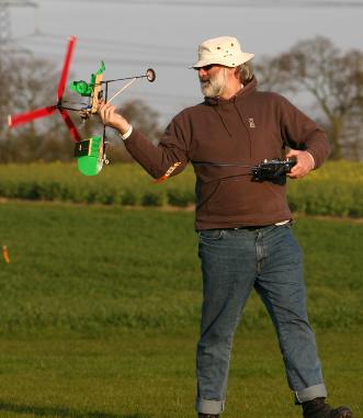
along them to produce a much greater glued area onto the main boom.| (Not) spinning up the rotors |
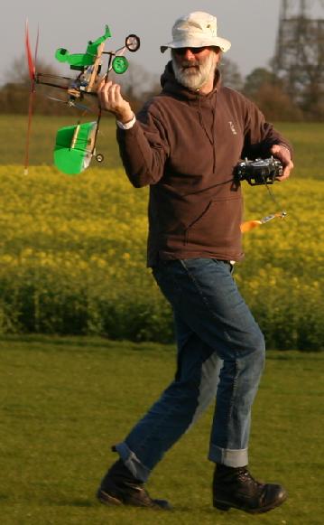
Running across the field |
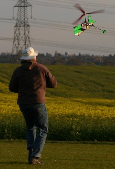
Off it goes |
 |
 |
 |