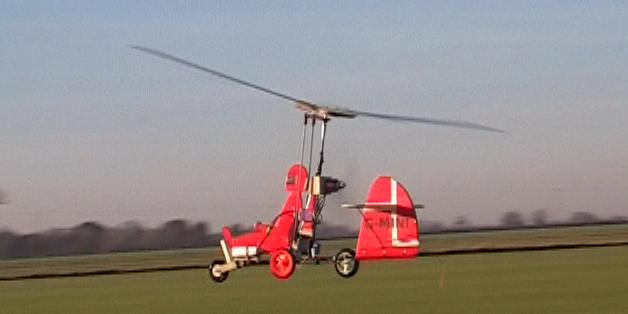
As you can see the build is
finished ! Here's the report on the maiden flight...
The weather today (29/11/08) wasn't ideal. At the field it was
overcast, cold and damp, but the wind was around 10mph.
I flew my MPX Gemini and my Rotorshape and to be honest the wind
conditions rather put me off trying the Minimum. Although the average
speed was ok, there were some quite strong gusts.
Anyway I did some "spin-up" tests. With the rotor tilted back the
blades spun up quickly and maintained speed when the airframe was
turned to a level position. I only needed to walk a few paces forward
and the blades spun up to flying speed and it was definitely trying to
lift out of my hand.
So next test I opened the throttle a little, just enough to overcome
the drag from the rotor. Now the model was trying to lift vertically
out of my hand, but it caught a gust and I nearly dropped it.
This put me off the idea of a hand launch.
Jochen's design doesn't have a rudder so ROG isn't an option for him,
but I have added a rudder to mine. I did a few taxi-tests to make sure
that the rudder had enough authority to keep the model straight during
a takeoff run even with a fixed nose wheel. It proved OK.
After a while the wind seemed to calm down a little so I plucked up
courage and decided to try a short "hop".
The breeze was still strong enough to get the rotor spinning with the
elevator stick pulled back, and once it started to move the speed
quickly increased. What took me by surprise was the low rotor speed at
which the model started to lift as it hit bumps in the grass. A little
more throttle and it smoothly lifted off I did think about landing
straight away but it was so stable that let it rise a bit further and
put it into a gentle left turn.... "It's so stable" I commented. I
think I said that about 10 times
I took it round two left hand circuits before bringing it gently down
to a landing....
It was very well behaved in the air, nothing unexpected and responded
as I expected to control inputs.
One flight was enough for me today. I'm sorry but there is no video of
the first flight.
BUILD LOG:
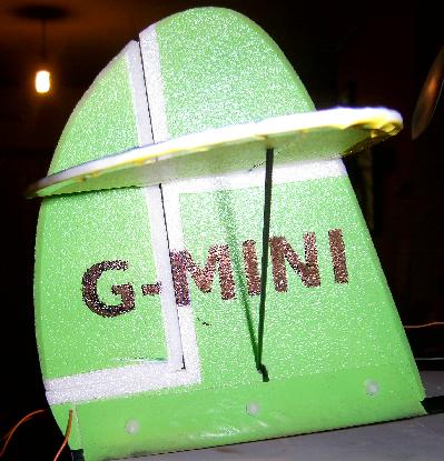
I've been getting the bits together for this for a long time, and
today I've finally got started on it! Hopefully I'll end up with
something that looks like this....
Information on this design can be found in the Autogyros section on RCGroups
I actually got started a few weeks ago when I visited a friend with a
scroll saw to cut out the ply and fibreglass (gf) parts to make the
head assembly.
The three upside down "U" shaped bits are the gf top and bottom and ply
middle that will make up the control horn "sandwich".
The twelve right most parts are the three sets of blade mounts and
stiffeners.
The two triangular parts are the top and bottom of the hub and the "Y"
shaped piece is the 0.5mm think gf that goes between them and makes the
flapping hinge.
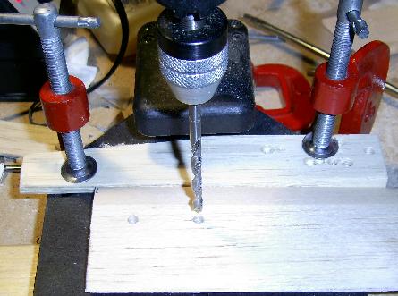
After drilling the 10mm holes in the centers of the hub parts I used
the drill bit to hold the parts in place while drilling the other
holes. This ensured that the holes were all drilled at the same
radius. Here you can see top and
bottom views of the hub assembled for the first time.
The next job was to glue the bearings into the top and bottom of the
hub. I had acquired some "UHU Plus Endfest 300", a two
part epoxy recommended by Jocken. Before attempting
to glue the bearings in place I protected them from the glue by
sticking small disks of PVC tape over their ends.
Here you can see that one end of one bearing has been roughly covered
and that I'm cutting out the second bearing which is stuck to the
underside of the white tape.
After roughly cutting them out I carefully trimmed back the extra tape
to prevent it getting in between the bearing and the plywood as the
bearing was being inserted into the hole in the wood. On the left
you can see the bearings ready to be glued into the hub.
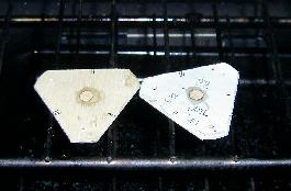
The UHU website gives details
on using Endfest and how it increases in bond strength if it is
"cooked". Here are the two hub parts
being "cooked" at gas mark 1 for 10 minutes.
While the oven was hot and I had some Endfest mixed up I glued together
the gf and ply sandwich that makes the control arm. Luckily
the plastic clamps didn't melt in the oven!
Well, when I came to put the hub together all was not well :(
Although I had been as careful as I could to get the bearings correctly
positioned in the ply wood they were not inline with each other.
The hub would spin freely until I did up the bolts then everything went
stiff. Also as it spun it wobbled a bit as well.
So I decided to build Hub No.2. This time I used some
thicker plywood so that the bearings are completely contained with in
the wood. I only roughly cut out the triangular shape so that I
wouldn't have wasted time shaping it if it turned out no better than
the first one. I protected the bearings as before, but this time
I only pushed the bearings half way into the holes with my fingers and
then lay them on a flat surface to push them fully into place.
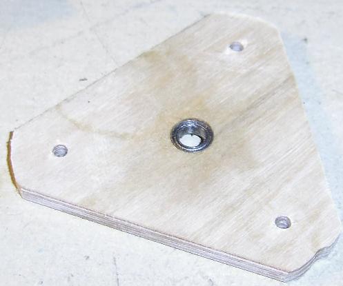
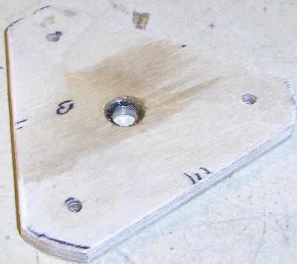
These two pictures are of
the bottom part of the hub. As you can see the bearing is flush
with bottom (left) and inset from the top (right).
The top part has the bearing flush with the top surface. I'm
going to put a washer between the top part and the thrust bearing so
that the lift is transfered via the wooden parts and not the bearing. Because the second hub is
made from thicker ply I've also had to make three more blade
mounts from the same thickness ply. Here they are just placed in
position. I've not put the 30 degree slant on the hub edges yet,
and I might put it on the blade mount edges instead.
Hub No. 2 is heavier than the first one, but I'm much happier about the
way it fits together and it spins freely on the bearings when it's all
bolted together.
I tried to follow Jochen's instructions for stiffening the trailing
edge of the blades, but due to the clink-film I used having no
resistance to CA I ruined a blade.... Maybe I'll write about that
bad experience one day !
Here is an off-cut of one
of the blades which has had the two 4mm holes drilled in it and
although you can't see them the brass collars have been inserted as
well. The purpose of this "test" was to check that I could glue
the gf reinforcements in place. As you can see the top one needs
to be bend into shape around the top surface of the blade. All that was needed was a
few clamps.
I cut out an extra pair of gf blade reinforers and glued them in place
on the off-cut. Since I wouldn't be able to get the blades into
the oven I set the piece in front of my gas fire to cure. To stop
the clamps getting stuck to the blade I smeared them with Vasaline.
I have a bad habit of putting too much glue on things and this was no
exception. After the epoxy had set there were several places
where the epoxy had run from around the edge of the reinforcer and set
in a "blob". While this just looked untidy on the top, on the
bottom surface it was a problem because the blobs prevented the blade
from resting flat on the pitch wedge. I used a
small grinding tool in my drill to remove the excess epoxy.
I realised that the most
important thing about the two holes in the blades was that they must be
the same distance back from the leading edge otherwise the blade will
not be correctly positioned. I used a simple fence on my drill to
ensure the holes were aligned. With the blade reinforcements in position I could now
fully assemble the rotors for the first time. You can see that on
one blade I tried to use some PVC tape to prevent the excess epoxy
sticking to the blade, but it made more of a mess. I havn't got
the correct bolts for securing the blades yet. On the underside
you can see the control arm and head pivot. I took the chance
when I had some spare epoxy mixed up to bind the ends of the horn with
some strong thread. You can see that I have cut to length the
bolts that hold the hub together because there isn't much clearance
between the bottom of the hub and the control arm.
UPDATE: I was never very happy with the rather small gap between
the top of the control horn and the bolts that hold the hub
together. The reduced clearance was one consequence of making the
hub No2 from the thicker plywood. I decided to have another
go at making a hub with the thinner ply as used in hub No1. I
followed the same process as for Hub No1, but when I put the bearings
in place I pressed them in by pressing the ply triangle against a flat
piece of metal. I even put two strips of PVC tape either side of
the hole to take acount of the thickness of the piece of PVC tape which
was already in place to keep the epoxy out of the bearing. The
parts were cooked as before and this time it all came out true.
The thinner ply (hubs 1+3) is 2.16mm thick, the thicker
ply (hub 2) is 4.35mm thick, so by using the thinner ply I gained
(4.35x2) - (2.16x2) = 4.38mm of extra
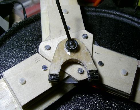
clearance. I also lost XXXg of weight ! There was now enough space below the hub to justify
making up the collar to lift the hub clear of the horn.
Here for comparison is the head for my Rotorshape.
The tail fin is mounted onto the rear boom using a "U"
shaped glass fibre bracket which wraps around the boom.
The bracket is made from some gf cloth soaked in epoxy resin.
The shape was formed using a simple jig which was made from a length of
6mm cf tube and some 6mm balsa to take the place of the 6mm depron
fin. The tube was glues to the balsa with CA.
A piece of polythene (an old
plastic bag) was layed over the jig to stop the epoxy sticking to the
jig. It was pulled down tight and held in place by the jaws of the vice.
Two pieces of gf cloth were used. One piece was placed on onto
the jig and epoxy resin worked into the weave, then the second piece
was layed over the first and more resin worked in.
A second piece of polythene was then placed over the jig and most of
the air bubbles worked out. To keep it all in place while the
resin set a piece of balsa was placed on either side and clamped in
place.
Once the resin had set it was easy to remove the formed "U" bracket
from the jig as the polythene sheets had done their job. The
final
step was to trim off the excess gf cloth and to drill three holes to
take 3mm bolts.
Here you can see the
finished "U" bracket placed around the boom and the depron fin
slid into place. It will b glued in place with some UHU-POR so
that it can be removed later to repair damage or to replace a broken
boom.
In a departure from Jochen's design I'm adding a rudder.
The hinge is made from 3M Blenderm tape and the
control horn was cut out from an old plastic ID card. It was
mounted by cutting a slit in the depron with a scalpel bade, running
some epoxy over the slit and pushing the horn through the slit until it
was flush with the other side. I've used this technique for the
rudder on my Rotorshapes.
The addition of the rudder means I've got to cut out a "V" shaped
section of the horizontal stabilisers. In the original design the
horizontal part was in one piece and the vertical part was cut in two,
but because of the rudder the vertical part is in one piece and the
horizontal part will be split by the vertical part. You'll see
what I mean when I've built it :)
Or maybe you won't see it.... Not everything went to plan, so now
I'm working on "Plan B"....
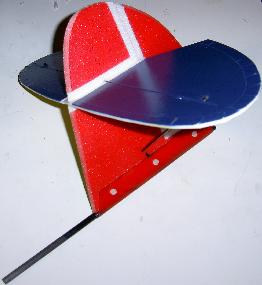
My plan to keep the vertical
fin in one piece and to split the horizontal stabilizer into two parts
failed. So here is the second try. Jochen adds
a thin (0.1mm) strip of cf around the edge of his horizontal stab. ,
but
I couldn't get any. So instead, to strengthen up the deron I've
inset a 0.5mm x 3mm cf strip and edged it with white PVC tape.
I wanted to make sure that I
didn't get any paint onto the sections
that would eventually be glued to the top and bottom parts of the
vertical fin, so I cut two small strips of depron (from the off
cuts)
and taped them in place over the parts that needed
protection from
paint. Doing it this way also avoided leaving a layer of adhesive
from
the PVC tape on the gluing area.
Here is the vertical fin
after its third layer of paint. You can see that I've masked off
the joins between the rudder and the fin and between the top and bottom
sections of the fin. As before this has kept paint away from the
parts that will be glued to the horizontal stab. and also the
area that will be covered by the tape used for the rudder hinge.
With the masking tape removed.
The horizontal stab. was held
in place with a couple of pins and weighted down with a few coins while
the glue set. I had taken great care to make sure the top edge of
the vertical fin was flat and true.
After some experimentation I used white wood glue (PVA) for the
joint. A test joint proved to be stronger than the depron itself
and it has the big advantage over CA of not setting instantly.
The bottom surface of the horizontal stab. is Yellow.
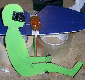
The pilot follows the same
colour scheme as the vertical fin. It has a core of 0.5mm gf with
3mm depron glued to each side. I drew on the "art work" before
spraying and I've used a black permanent marker pen for the visor and
control stick.
Here are a couple of shots of the completed tail mounted on its boom
Jochen's instructions show
to use a simple collar at the top of the
mast to secure the joint in place in the 5mm cf tube. I was
discussing
this with a friend of mine who has a lathe, and he offered to machine
up a part to replace the simple collar at the top of the rotor
mast.
The intent was to increase the security and to spread the load a bit
better.
He produced a tapered collar and a small brass insert to match the
radius of the joint arm to the inside radius of the cf rod.
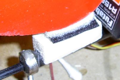
Here it the sleeve in
place.
The notches in the shaft for the grub screws are aligned with the
axis of the joint which means that the mast needs to be glued
into the bottom of the airframe in the correct orientation. Here the bottom of the
airframe has been drilled (more on that later) and put into my vice
such that the rotor mast sits horizontal. Two long nylon bolts
and been screwed into the holes where the grub screws would normally go
so that the mast can be glued into the bottom part with the correct
orientation. I will get it better positioned before the glue is
applied!
Actually I decided to do this a bit differently.
To get the alignment correct I realised I could screw the mast down to
a piece of board using the threaded holes in the collar. Here you
can see the first stage in glueing the airframe together. The
screw stops the mast from rolling out of alignment and
holds the screw holes at right angles to the bottom section. It
also keeps all the parts in postion over the plan while getting
everything in place. The three wooden strips have been sanded to
the correct thickness to keep everything level .
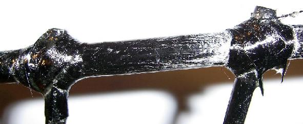
The parts were initially glued in place using thin CA.
The joints were
finally bound with some carbon fiber tape and epoxy resin. This
was a very messy process! With hindsight it would have been
much easier if I had clamped the airframe in a vice rather than trying
to hold it in gloved hands that were getting increasingly covered in
epoxy resin. I'm quite pleased with the final outcome though.
With the airframe taking shape I next built
the motor mount. The picture is taken from above. The
"not quite quadrants" were made bu cutting some rectangluar section
from corner to corner.
The parts that go either side of the mast were bolted in place first
then the other parts were glued on so that there is no inbuilt stress
caused by mast.
The motor mount is designed to allow the
motor to be offset to the right to counter the yaw induced by the prop
wash over the fin/rudder.
Here the motor has been temporarily fitted to the motor mount to allow
the offset to be tested. The mast is supported in a thrust
bearing at the top so the airfame can spin around freely. For the
test the rudder was taped in it's neutral position.
The motor was mounted on a
separate piece of 3mm ply wich was held to the main mount with rubber
bands. The offset was adjusted until the model didn't swing to
the left or right when the motor was running.
Finally the motor was fixed in place with a couple of bolts. This
isn't quite how I intended it to look but until I've flown it to see if
the offset is correct it will have to do.
The front wheel assembly caused me a few problems. I couldn't
quite picture how it was supposed to go together from reading just the
instructions. Jochen kindly took some pictures of the
finished assembly and emailed them to me, then it all became clear.
I only had two wheels of
the right size so I modified the mount to take a smaller diameter
wheel. Here is the template I made to take a smaller front wheel
and still maintain the airframe level on the ground.
I have used the square
section carbon rod as described in the construction notes. The
collet I used was a 1/4" dubro part which still required the front part
of the rod to be sanded round (but not as much carbon needed to be
removed).
The cut outs for the collet in the front of the wooden parts was made
with a suitably sized sanding drum on my dremmel.
I couldn't find any carbon fibre sheet to make the wheel supports so I
used 1mm glass fibre. Here the wheel supports are being glued
(with UHU-POR) to the wodden parts.
The real strength
comes from the carbon fiber tape which is wetted with epoxy resin and
then wrapped around supports.
A piece of 4mm ply was cut out and shaped to fit snugly
into the airframe. The position of the servos was
determined so that the control rods (drawn on in white) will normally
be positioned at right angles to the ball joints at the top.
Before the ply was glued in place with some epoxy, the areas where the
servo mounts and the servos themselves touch the wood were covered with
PVC tape to prevent any epoxy that might have run from making the
surface uneven.
The rudder servo is held
inplace with hot glue.
The rudder control horn was cut out from an old magnetic stripe vending
machine card and glued in place with some epoxy.
Inorder to get the
undercarriage correctly positioned I made up a simple support by
drilling a hole in a block of balsa. With the bottom of the
airframe pushed into the hole I could carefully position the airframe
over the undercarriage and line it all up with the marks which you can
see drawn on the paper.
A small "blob" of epoxy was used initially to hold it all in place.
Once the epoxy had hardened the real joint was made with carbon fibre
ribon wetted with epoxy resin. In the picture you can see that I
also strengthened the ends of the support by wrapping them with a thick
cotton which was then soaked in CA to hold it in place.
Jochen must have some
smaller diameter heat shrink tube because mine would not fit into the
support witout shrinking it a little with my heat gun. I also slightly rounded
the edges of the hole in the end of the support so as not to create too
much stress where the wheel axel exited the support.
Pilot Mounting
The pilot is attached at three points. His feet fit into a slot
made from two pieces of balsa quadrant mounted on a piece of balsa that
is glued between the sides of the front wheel support brackets.
His head is velcroed to a head rest that is glued between the sides of
the motor mount.
His bottom is velcroed to a small balsa block that is glued to the
airframe. The underside of the block is shaped to match the curve
of the carbon rod.
Post Maiden Registration
Second flight
A little bit of maths: Setting up the transmitter
Jochen's instructions give the following angles:
Hang
angle:
-8°
Roll:
±15°
Pitch:
-7°/+8°
Motor torque compensation: 0°/6° to the right
Blade angle of incidence: -2.3°
Here is how I setup the Roll and Pitch angles. This needs the
servos and radio installed and working.
Check that all trims are set to neutral position and rates and
endpoints are set to 100%.
Use the sub-trim to get the two servo arms aligned.
With the model sitting on a level surface turn the rotor until one
blade in pointing to the front.
Measure the height of the rotor tip with the elevator stick neutral,
fully up and fully down.
Now turn the rotor until one blade is pointing to the side (either side
will do).
Measure the height of the rotor tip with the aileron stick neutral,
fully left and fully right.
You also need to measure the radius of the blades.
Unfortunatley I can't find the set of measurements I took with
everything set to 100%. However I do know that they showed the
pitch change angle was too small but the roll change angle
was too large. So as a guess I increased all the end
points to maximum (125%) and reduced the aileron rates to 50%
Here are the second set of measurements I took. (All measurments are in
mm)
Radius 490
Max Up 472 Level 390 Max Down
306
Change up = 472 - 390 = 82
Change down 390 - 306 = 84
Roll Left 405 Level 310 Roll Right 220
Change Left = 405 - 310 = 95
Change Right = 310 - 220 = 90
Here's the bit of maths....
The Pitch angles are arctan(82/490) =
9.5deg and arctan(84/490) = 9.7deg
The Roll angles are arctan(95/490) = 11.0 deg and arctan(90/490) =
10.4deg
Now he Roll angle was too small and the pitch angle too large !
(Well it was only a guess!)
I was a little unhappy running the endpoints at maximum so I changed
the servo arms for some wich were a little bit longer.
With the longer arms installed I remeasured and recalculated the angles.
The pitch was still too large so I reduced the endpoints from 125% to
118% to give the correct angles.
Having done that the roll was too small, so I increased the roll rate
from 50% to 89% to give the correct angles.
Sad news
24th April 2011:
I learned a few weeks ago that Jocken had passed away. Many
tributes to him have been posted on RC Groups.
Unfortunatley I was unable to fly my Minimum in his honour because it
had a damaged rotor blade. So yesterday I fixed it.
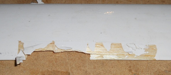
Last Spring (2010) I took it out early one morning for a flight, but
the very low sun caused me to loose orientation. In the
enevitable "falling from the sky" that followed one of the rotor blade
mounting bolts snapped (as they are supposed to do) but the blade then
rotated back so far that the trailing edge hit the top of the hub
mounting. As the picture shows this damaged the trailing edge.
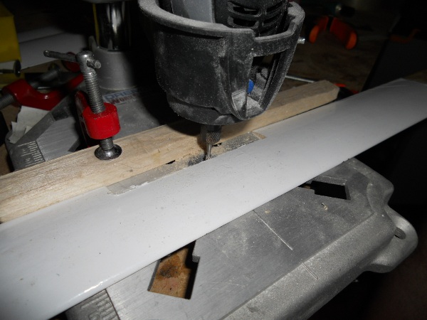
First job was to cut out the damaged section (about 9cm in
length).
I cut the bulk of the wood out with a balsa saw, then set up my dremmel
with a milling tool and a guide stop inorder to produce a clean edge.
Luckily I had kept the the original blade off-cuts so it was just a
matter of cutting out a slightly oversize insert, then sanding it to
fit, and running some thin cyano into the join. The blades were
originally cut to length after the trailing edges had been "drooped" so
the insert needed no further work. The repaired blade is now very
slightly (0.1g) heavier than the other two, but it didn't produce any
noticable shaking in flight.
 As you can see the build is
finished ! Here's the report on the maiden flight...
As you can see the build is
finished ! Here's the report on the maiden flight...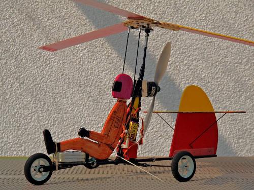


 Here you can see top and
bottom views of the hub assembled for the first time.
Here you can see top and
bottom views of the hub assembled for the first time.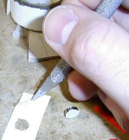

 Here are the two hub parts
being "cooked" at gas mark 1 for 10 minutes.
Here are the two hub parts
being "cooked" at gas mark 1 for 10 minutes.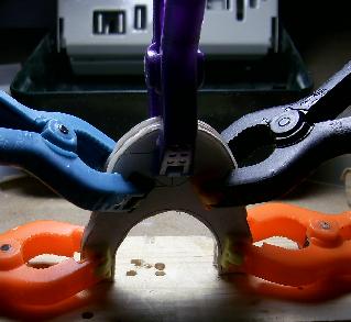
 These two pictures are of
the bottom part of the hub. As you can see the bearing is flush
with bottom (left) and inset from the top (right).
These two pictures are of
the bottom part of the hub. As you can see the bearing is flush
with bottom (left) and inset from the top (right). Because the second hub is
made from thicker ply I've also had to make three more blade
mounts from the same thickness ply. Here they are just placed in
position. I've not put the 30 degree slant on the hub edges yet,
and I might put it on the blade mount edges instead.
Because the second hub is
made from thicker ply I've also had to make three more blade
mounts from the same thickness ply. Here they are just placed in
position. I've not put the 30 degree slant on the hub edges yet,
and I might put it on the blade mount edges instead. Here is an off-cut of one
of the blades which has had the two 4mm holes drilled in it and
although you can't see them the brass collars have been inserted as
well. The purpose of this "test" was to check that I could glue
the gf reinforcements in place. As you can see the top one needs
to be bend into shape around the top surface of the blade.
Here is an off-cut of one
of the blades which has had the two 4mm holes drilled in it and
although you can't see them the brass collars have been inserted as
well. The purpose of this "test" was to check that I could glue
the gf reinforcements in place. As you can see the top one needs
to be bend into shape around the top surface of the blade.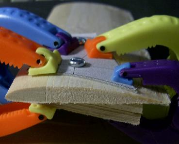 All that was needed was a
few clamps.
All that was needed was a
few clamps.
 I realised that the most
important thing about the two holes in the blades was that they must be
the same distance back from the leading edge otherwise the blade will
not be correctly positioned. I used a simple fence on my drill to
ensure the holes were aligned.
I realised that the most
important thing about the two holes in the blades was that they must be
the same distance back from the leading edge otherwise the blade will
not be correctly positioned. I used a simple fence on my drill to
ensure the holes were aligned.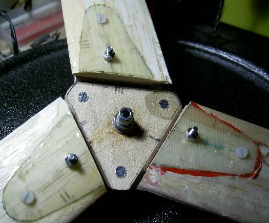
 With the blade reinforcements in position I could now
fully assemble the rotors for the first time. You can see that on
one blade I tried to use some PVC tape to prevent the excess epoxy
sticking to the blade, but it made more of a mess. I havn't got
the correct bolts for securing the blades yet. On the underside
you can see the control arm and head pivot. I took the chance
when I had some spare epoxy mixed up to bind the ends of the horn with
some strong thread. You can see that I have cut to length the
bolts that hold the hub together because there isn't much clearance
between the bottom of the hub and the control arm.
With the blade reinforcements in position I could now
fully assemble the rotors for the first time. You can see that on
one blade I tried to use some PVC tape to prevent the excess epoxy
sticking to the blade, but it made more of a mess. I havn't got
the correct bolts for securing the blades yet. On the underside
you can see the control arm and head pivot. I took the chance
when I had some spare epoxy mixed up to bind the ends of the horn with
some strong thread. You can see that I have cut to length the
bolts that hold the hub together because there isn't much clearance
between the bottom of the hub and the control arm.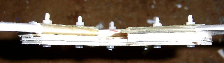 The thinner ply (hubs 1+3) is 2.16mm thick, the thicker
ply (hub 2) is 4.35mm thick, so by using the thinner ply I gained
(4.35x2) - (2.16x2) = 4.38mm of extra
clearance. I also lost XXXg of weight !
The thinner ply (hubs 1+3) is 2.16mm thick, the thicker
ply (hub 2) is 4.35mm thick, so by using the thinner ply I gained
(4.35x2) - (2.16x2) = 4.38mm of extra
clearance. I also lost XXXg of weight !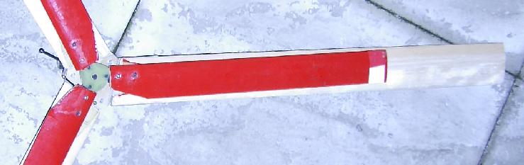
 The tail fin is mounted onto the rear boom using a "U"
shaped glass fibre bracket which wraps around the boom.
The tail fin is mounted onto the rear boom using a "U"
shaped glass fibre bracket which wraps around the boom. A piece of polythene (an old
plastic bag) was layed over the jig to stop the epoxy sticking to the
jig. It was pulled down tight and held in place by the jaws of the vice.
A piece of polythene (an old
plastic bag) was layed over the jig to stop the epoxy sticking to the
jig. It was pulled down tight and held in place by the jaws of the vice.
 Here you can see the
finished "U" bracket placed around the boom and the depron fin
slid into place. It will b glued in place with some UHU-POR so
that it can be removed later to repair damage or to replace a broken
boom.
Here you can see the
finished "U" bracket placed around the boom and the depron fin
slid into place. It will b glued in place with some UHU-POR so
that it can be removed later to repair damage or to replace a broken
boom. My plan to keep the vertical
fin in one piece and to split the horizontal stabilizer into two parts
failed. So here is the second try. Jochen adds
a thin (0.1mm) strip of cf around the edge of his horizontal stab. ,
but
I couldn't get any. So instead, to strengthen up the deron I've
inset a 0.5mm x 3mm cf strip and edged it with white PVC tape.
My plan to keep the vertical
fin in one piece and to split the horizontal stabilizer into two parts
failed. So here is the second try. Jochen adds
a thin (0.1mm) strip of cf around the edge of his horizontal stab. ,
but
I couldn't get any. So instead, to strengthen up the deron I've
inset a 0.5mm x 3mm cf strip and edged it with white PVC tape.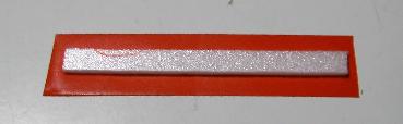 I wanted to make sure that I
didn't get any paint onto the sections
that would eventually be glued to the top and bottom parts of the
vertical fin, so I cut two small strips of depron (from the off
cuts)
and taped them in place over the parts that needed
protection from
paint. Doing it this way also avoided leaving a layer of adhesive
from
the PVC tape on the gluing area.
I wanted to make sure that I
didn't get any paint onto the sections
that would eventually be glued to the top and bottom parts of the
vertical fin, so I cut two small strips of depron (from the off
cuts)
and taped them in place over the parts that needed
protection from
paint. Doing it this way also avoided leaving a layer of adhesive
from
the PVC tape on the gluing area. 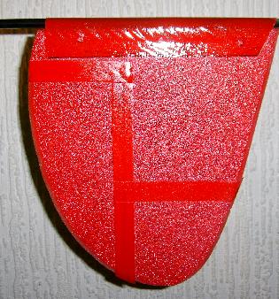 Here is the vertical fin
after its third layer of paint. You can see that I've masked off
the joins between the rudder and the fin and between the top and bottom
sections of the fin. As before this has kept paint away from the
parts that will be glued to the horizontal stab. and also the
area that will be covered by the tape used for the rudder hinge.
Here is the vertical fin
after its third layer of paint. You can see that I've masked off
the joins between the rudder and the fin and between the top and bottom
sections of the fin. As before this has kept paint away from the
parts that will be glued to the horizontal stab. and also the
area that will be covered by the tape used for the rudder hinge.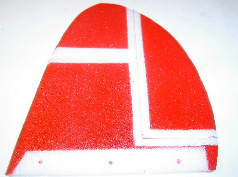 With the masking tape removed.
 The horizontal stab. was held
in place with a couple of pins and weighted down with a few coins while
the glue set. I had taken great care to make sure the top edge of
the vertical fin was flat and true.
The horizontal stab. was held
in place with a couple of pins and weighted down with a few coins while
the glue set. I had taken great care to make sure the top edge of
the vertical fin was flat and true.
 The pilot follows the same
colour scheme as the vertical fin. It has a core of 0.5mm gf with
3mm depron glued to each side. I drew on the "art work" before
spraying and I've used a black permanent marker pen for the visor and
control stick.
The pilot follows the same
colour scheme as the vertical fin. It has a core of 0.5mm gf with
3mm depron glued to each side. I drew on the "art work" before
spraying and I've used a black permanent marker pen for the visor and
control stick.
 Jochen's instructions show
to use a simple collar at the top of the
mast to secure the joint in place in the 5mm cf tube. I was
discussing
this with a friend of mine who has a lathe, and he offered to machine
up a part to replace the simple collar at the top of the rotor
mast.
The intent was to increase the security and to spread the load a bit
better.
Jochen's instructions show
to use a simple collar at the top of the
mast to secure the joint in place in the 5mm cf tube. I was
discussing
this with a friend of mine who has a lathe, and he offered to machine
up a part to replace the simple collar at the top of the rotor
mast.
The intent was to increase the security and to spread the load a bit
better. Here it the sleeve in
place.
Here it the sleeve in
place. Here the bottom of the
airframe has been drilled (more on that later) and put into my vice
such that the rotor mast sits horizontal. Two long nylon bolts
and been screwed into the holes where the grub screws would normally go
so that the mast can be glued into the bottom part with the correct
orientation. I will get it better positioned before the glue is
applied!
Here the bottom of the
airframe has been drilled (more on that later) and put into my vice
such that the rotor mast sits horizontal. Two long nylon bolts
and been screwed into the holes where the grub screws would normally go
so that the mast can be glued into the bottom part with the correct
orientation. I will get it better positioned before the glue is
applied! 
 The joints were
finally bound with some carbon fiber tape and epoxy resin. This
was a very messy process! With hindsight it would have been
much easier if I had clamped the airframe in a vice rather than trying
to hold it in gloved hands that were getting increasingly covered in
epoxy resin. I'm quite pleased with the final outcome though.
The joints were
finally bound with some carbon fiber tape and epoxy resin. This
was a very messy process! With hindsight it would have been
much easier if I had clamped the airframe in a vice rather than trying
to hold it in gloved hands that were getting increasingly covered in
epoxy resin. I'm quite pleased with the final outcome though. taking shape I next built
the motor mount. The picture is taken from above. The
"not quite quadrants" were made bu cutting some rectangluar section
from corner to corner.
taking shape I next built
the motor mount. The picture is taken from above. The
"not quite quadrants" were made bu cutting some rectangluar section
from corner to corner.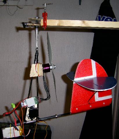 is designed to allow the
motor to be offset to the right to counter the yaw induced by the prop
wash over the fin/rudder.
is designed to allow the
motor to be offset to the right to counter the yaw induced by the prop
wash over the fin/rudder.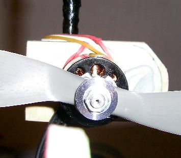 The motor was mounted on a
separate piece of 3mm ply wich was held to the main mount with rubber
bands. The offset was adjusted until the model didn't swing to
the left or right when the motor was running.
The motor was mounted on a
separate piece of 3mm ply wich was held to the main mount with rubber
bands. The offset was adjusted until the model didn't swing to
the left or right when the motor was running.
 I only had two wheels of
the right size so I modified the mount to take a smaller diameter
wheel. Here is the template I made to take a smaller front wheel
and still maintain the airframe level on the ground.
I only had two wheels of
the right size so I modified the mount to take a smaller diameter
wheel. Here is the template I made to take a smaller front wheel
and still maintain the airframe level on the ground. 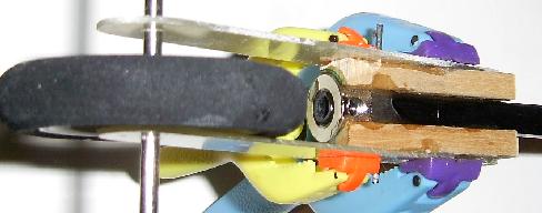 I have used the square
section carbon rod as described in the construction notes. The
collet I used was a 1/4" dubro part which still required the front part
of the rod to be sanded round (but not as much carbon needed to be
removed).
I have used the square
section carbon rod as described in the construction notes. The
collet I used was a 1/4" dubro part which still required the front part
of the rod to be sanded round (but not as much carbon needed to be
removed).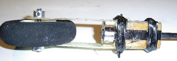 The real strength
comes from the carbon fiber tape which is wetted with epoxy resin and
then wrapped around supports.
The real strength
comes from the carbon fiber tape which is wetted with epoxy resin and
then wrapped around supports. 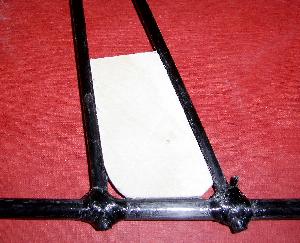
 A piece of 4mm ply was cut out and shaped to fit snugly
into the airframe. The position of the servos was
determined so that the control rods (drawn on in white) will normally
be positioned at right angles to the ball joints at the top.
A piece of 4mm ply was cut out and shaped to fit snugly
into the airframe. The position of the servos was
determined so that the control rods (drawn on in white) will normally
be positioned at right angles to the ball joints at the top.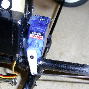
 The rudder servo is held
inplace with hot glue.
The rudder servo is held
inplace with hot glue. Inorder to get the
undercarriage correctly positioned I made up a simple support by
drilling a hole in a block of balsa. With the bottom of the
airframe pushed into the hole I could carefully position the airframe
over the undercarriage and line it all up with the marks which you can
see drawn on the paper.
Inorder to get the
undercarriage correctly positioned I made up a simple support by
drilling a hole in a block of balsa. With the bottom of the
airframe pushed into the hole I could carefully position the airframe
over the undercarriage and line it all up with the marks which you can
see drawn on the paper. 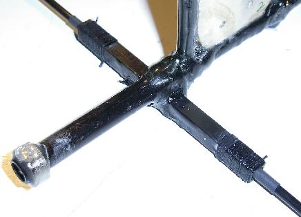
 Jochen must have some
smaller diameter heat shrink tube because mine would not fit into the
support witout shrinking it a little with my heat gun.
Jochen must have some
smaller diameter heat shrink tube because mine would not fit into the
support witout shrinking it a little with my heat gun. I also slightly rounded
the edges of the hole in the end of the support so as not to create too
much stress where the wheel axel exited the support.
I also slightly rounded
the edges of the hole in the end of the support so as not to create too
much stress where the wheel axel exited the support.