The LA-Heli Rotorshape
Sometime last year I was looking at the Robot Birds web site and I
came across their web page for the Rotorshape
from LA-heli. I just
had to have one!
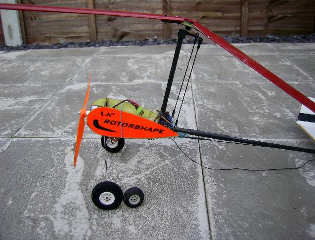
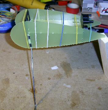 This is the body of the
Rotorshape. It's just two tear-drop shaped sides, a platform for
the battery, a mount for the motor and undercarriage and a mount for
the two rotor control servos.
This is the body of the
Rotorshape. It's just two tear-drop shaped sides, a platform for
the battery, a mount for the motor and undercarriage and a mount for
the two rotor control servos.
 The parts are glued together with CA,
but I decided to add some extra reinforcements in the form of some
balsa strips to increase the gluing area.
The parts are glued together with CA,
but I decided to add some extra reinforcements in the form of some
balsa strips to increase the gluing area.
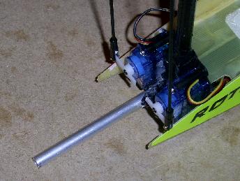
 I didn't take many pictures during the
build, but here it is with the motor installed, the main boom and rotor
mast fitted (both carbon tubes) and the head assembled thought the
blades had not yet been covered.
I didn't take many pictures during the
build, but here it is with the motor installed, the main boom and rotor
mast fitted (both carbon tubes) and the head assembled thought the
blades had not yet been covered.
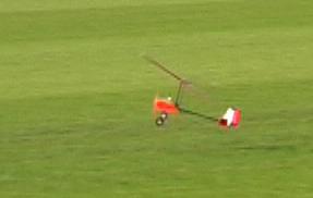
 Imfact I didn't take any more
pictures until after it had flown a few times. The maiden
was carried out on a day when the wind was really a bit too strong, but
it flew well from it's first launch. The small wheels mean that
on a grass field the only practical way to get it flying is with a hand
launch.
Imfact I didn't take any more
pictures until after it had flown a few times. The maiden
was carried out on a day when the wind was really a bit too strong, but
it flew well from it's first launch. The small wheels mean that
on a grass field the only practical way to get it flying is with a hand
launch.
It took quite a few flights to get used to its flying
characteristics. Although you fly it like a conventional fixed
wing model (with alierons and elevator on the right stick), the way it
reacts to control inputs takes a while to learn. I can best
describe it as being "radio guided" rather than "radio
controlled". There is quite a delay between the control input and
the model reacting as it "wobbles around the sky". Since
there very little to actualy see in the sky it is very easy to get
disorientated and not know in which direction it is actually
pointing. Consequently I crashed it several times as a result of
it getting a bit to far away and then rolling it the wrong
way. Quite remarkably these crashes often resulted in no damage
at all, but once the rotor mast shapped and later the main boom snapped
as shown on the right.
 The repair was quite simple. The
boom was snapped off and a short section of aluminium tube glued (with
epoxy) inside the carbon tube. The fit was quite close so I put
some epoxy into the ends of the carbon tube so that it would be spread
along the aluminium as it was inserted.
The repair was quite simple. The
boom was snapped off and a short section of aluminium tube glued (with
epoxy) inside the carbon tube. The fit was quite close so I put
some epoxy into the ends of the carbon tube so that it would be spread
along the aluminium as it was inserted.
 I spread a thin film of epoxy onto the rod before
putting it together and the excess neatly joined the carbon tube ends.
I spread a thin film of epoxy onto the rod before
putting it together and the excess neatly joined the carbon tube ends.
 After I had been flying the Rotorshape
for a few weeks, I decided to add a rudder to improve the
control. Although it flew well without a rudder, it is now much
easier to control in turns. The rudder was made from a
piece of "pizza base", the control horn was cut out of an old vending
machine card and epoxied into a slot cut in the rudder. The
hinge is nothing more than a strip of PVC tape. There
was space in the fuzelage just infront of the rotor mast to mount
a small 5g servo.
After I had been flying the Rotorshape
for a few weeks, I decided to add a rudder to improve the
control. Although it flew well without a rudder, it is now much
easier to control in turns. The rudder was made from a
piece of "pizza base", the control horn was cut out of an old vending
machine card and epoxied into a slot cut in the rudder. The
hinge is nothing more than a strip of PVC tape. There
was space in the fuzelage just infront of the rotor mast to mount
a small 5g servo.
 The long contro rod had to be
repositioned as at first the rotor blades sometimes hit the rod at
ripped the horn out of the rudder.
The long contro rod had to be
repositioned as at first the rotor blades sometimes hit the rod at
ripped the horn out of the rudder.
 The small wheels and narrow width
of the undercarriage mean that landings must be directly into wind
otherwise the model tends to topple over. The blades are held in
place with small sacrificial balsa pegs, which break when the blade
tips hit the ground and save the blades from damage. The small
wheels and lack of a steerable tail wheel also mean the land launching
is the only viable means of take off. Even in a slight
breeze the rotors can be spun up to almost flying speed by holdiing the
model nose up, then only a few paces at walking speed will be needed to
get the rotors up to full speed. Mine only needs half
throttle and a gentle "push into the air" to launch.
The small wheels and narrow width
of the undercarriage mean that landings must be directly into wind
otherwise the model tends to topple over. The blades are held in
place with small sacrificial balsa pegs, which break when the blade
tips hit the ground and save the blades from damage. The small
wheels and lack of a steerable tail wheel also mean the land launching
is the only viable means of take off. Even in a slight
breeze the rotors can be spun up to almost flying speed by holdiing the
model nose up, then only a few paces at walking speed will be needed to
get the rotors up to full speed. Mine only needs half
throttle and a gentle "push into the air" to launch.


 Click
on this image to get to a video of my Rotorshape flying.
Click
on this image to get to a video of my Rotorshape flying.
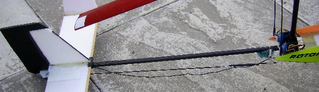
Rudder Modifications
In the pictures above you can clearly see the rudder control rod above
the main boom. In this position is is rather vulnerable to rotor
strikes if the model tips over when landing. The shock to
the servo when this happens has so far stripped the gears on three
servos. I've also had to replace the rudder once and re-glue the
control horn twice.
So, I decided to alter things so that the rudder control rod now lies
underneath the main boom which will hopefully protect it from rotor
strikes.
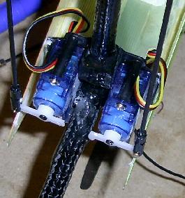
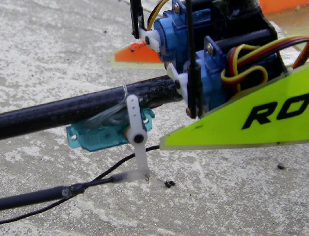 The load on the servo is quite
small so I chose to simply attach the servo to the main boom with "hot
glue". Although this has moved the servo back further behind the
CofG it's still close ehough not to have made any noticable difference
to the trim.
The load on the servo is quite
small so I chose to simply attach the servo to the main boom with "hot
glue". Although this has moved the servo back further behind the
CofG it's still close ehough not to have made any noticable difference
to the trim.
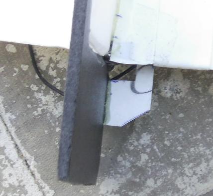
The rudder control horn needed to be enlarged as it needs to clear the
back end of the main boom which is immediatley ahead of the front edge
of the rudder surface below the horizontal
stabiliser. As before the control surface was cut out from
a "pizza base", the control horn is a piece from an old magantic strip
payment card and it is held in the rudder with some epoxy. The
hinge is made from "blenderm" tape.
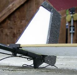 I've added a small skid to the
bottom of the boom to stop the bottom of the rudder touching the
ground. Looking at the picture I think I still need to trim off
the bottom edge of the rudder a bit more.
I've added a small skid to the
bottom of the boom to stop the bottom of the rudder touching the
ground. Looking at the picture I think I still need to trim off
the bottom edge of the rudder a bit more.
Bigger Wheels
One evening in very calm winds I tried a "touch and go" for the first
time. It wasn't really planned it just happened. After a
landing the rotor was still spinning and I just opened up the throttle
again and off it went :) Next time round I kept it moving on the
ground, opened it up and off it went again :) So, having
mastered touch and goes, a few days later I decided to try a
take-off from a standing start. The wind was about 10mph and with
it sitting on the ground with
the rotor tilted all the way back it was spinning up quite fast so I
was sure I could get it to fly off the ground. The biggest problem was
that to start with the small wheels were getting stuck in the uneven
grass, but once the
rotor started to produce some lift it could start to move forward
without
nosing over. With the rudder I was able to keep it
pointing directly into the breeze, and once moving forward the rotor
quickly spun up to flying speed and it lifted off smoothly without
rolling either way. The cure to the problem caused by the small
wheels was obvious... fit some bigger wheels !
On my way home from work yesterday I had dropped into my LHS to get
some glues and as I looked at the racks of "stuff" I spotted some foam
wheels that looked about the right size....
Here you can see the old and new wheels for comparison. The old
ones were 35mm dia. and the new ones are 50mm dia. I used acouple
of short pieces of carbon rod to make up adapters to match the
wire diameter to the (larger) hole in the wheels.
If you look very closely you can see the tail boom has aquired an outer
sleeve over the spot where I snapped it a few weeks ago !
 With the original wheels and an 8" prop
there was very little ground clearance. You can see the tip of
the prop has a green stain from all the grass it has been cutting while
going touch and goes !
With the original wheels and an 8" prop
there was very little ground clearance. You can see the tip of
the prop has a green stain from all the grass it has been cutting while
going touch and goes !
The bigger wheels have several advantages:
They run much better on a grass surface and don't get stuck between the
grass.
The prop ground clearance is increased to the point were the prop
doesn't strike the ground when the tail lifts during a take-off run.
The model sits more "nose up" on the ground which makes it easier to
spin up the rotor in a breeze and makes a take-off run shorter.
Click the picture below for a video.
The improvements were immediatley obvious when I first opened the
throttle with the model sitting on the grass. Without hesitation
it started to move forward and I found it could easily be steered with
the rudder (even without a steerable tail wheel). At first
there wasn't enough breeze to spin up the rotor but I patiently
waited for a thermal to come through. A quick spin with my
"digital pre-rotator" (*), and with the elevator stick all
the way back, it set off across the grass. It was surprised how
quickly the rotor spun up to flying speed but I managed to release the
elevator stick soon enough to prevent a premature lift-off. It
rose slowly into the air at which point a bit more throttle put it into
a steady climb :)
(*) My Finger !
Throttle to Aileron mix
When I tried a "dead stick" landing the other week I found the model
rolled quite sharply to the right when I closed the throttle. I
carefully noted how much left stick I needed (about 40%) to keep it
straight and how much throttle it needed to fly straight and level
(50%). I then set up two of the programmable mixes on
my Futaba FF7 to mix some throttle into the aileron.
I set the mix's "offset" to 50%, so at cruise throttle the
mix would make no difference to the ailerons. I had to guess on
the percentages for the mix but set them at 20% as a first guess.
The first thing I tried in flight was to switch on the mix when flying
straight and level to check that the offst point was correct. As
I hoped this made no difference to the trim.
Next I tried slowly reducing the throttle to check the mix percentage
was correct. However 20% was too much as the model now rolled
slightly to the left. After a couple of adjustments I've
settled on 15%. Now I can perform "dead stick" landings
without problems.