LA Heli Rotorshape No. 2
Eventually my first Rotorshape broke it's rotor mast again. This
time it wasn't possible to get the mast to relocate correctly in the
mount so it was time time to build up my spare kit.
I decided to make a few modifications based on my experience with the
first one.
Wider undercarriage to make ROG and landings easier on rougher
surfaces.
 The original undercarriage was 8"
wide which is OK for use on smooth surfaces as long as take-offs and
landings can be performed directly into the wind.
The original undercarriage was 8"
wide which is OK for use on smooth surfaces as long as take-offs and
landings can be performed directly into the wind.
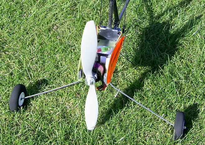
The wider undercarriage is made from some 14 s.w.g. (2mm) wire bent to
shape. The new wire is still mounted in the original
firewall/motor mount so the "apex bend" still had to be 90
degrees. I wanted to maintain the same nose height on the ground
so an extra bend was added in the wire just below the point where it
exited the motor mount. The final shape resulted in an 11" wheel
spacing.
The picture also shows the extra balsa quadrant I glued to many of the
joints to give then some extra strength,
 I also decided to use a different
motor and prop for this version.
I also decided to use a different
motor and prop for this version.
The motor is a Hacker A20-26M and the prop is an APC-E 8"x3.8".
The wheels are the larger 55mm ones I had fitted to the previous model
to improve the ground handling.

The motor has four tapped holes on its back plate, and two of them
lined up with the exisiting holes in the motor mount. The
instructions show to fix a couple of captive nuts
into the motor
mount, but because I had decided to use this motor before I glued the
mount together I didn't glue the nuts in place. The motor is held
in
place with a pair of bolts through the motor mount. Their heads
are
just reachable with a long thin screw driver.
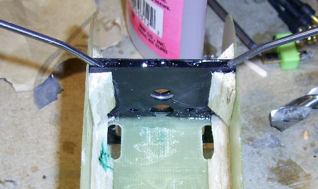
Strengthening the bracket that holds the rotormast.
 This is the plastic part that forms the
back of the fuzelarge. The tail boom passes through the hole in
the front and the rotor mast is held in the collar at the top.
This part eventually snapped on my first rotorshape.
This is the plastic part that forms the
back of the fuzelarge. The tail boom passes through the hole in
the front and the rotor mast is held in the collar at the top.
This part eventually snapped on my first rotorshape.
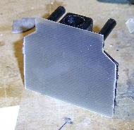 I made a "doubler" from some of the
0.5mm gf sheet I had purchased to make the hinges on my Minimum (not
yet started). I used epoxy resin to attach this to the front of
the part and then cut out the hole for the boom.
I made a "doubler" from some of the
0.5mm gf sheet I had purchased to make the hinges on my Minimum (not
yet started). I used epoxy resin to attach this to the front of
the part and then cut out the hole for the boom.
I also trimmed 0.5mm from the back edge of the gf sheet that makes the
bottom of the battery box to take account of the extra
thickness .
Bracing the rotormast and tail boom against each other.
On my first rotorshape both the tail boom and the rotormast had been
broken close to the points where they are held in the
bracket. To share any "shocks" between the two carbon tubes
I decided to add a brace between the two tubes.
 The brace is made from a piece of the same carbon tube as
the mast and boom. The ends of the brace was shaped using a round
file so that they fit around the boom and mast. Then brace was
initiall held in place with a few drops of thin CA, then the joint
areas were covered with epoxy and wrapped with "extra strong
polyester/cotton thread". Extra epoxy was smeered over the
outside of the thread to finish off the joint.
The brace is made from a piece of the same carbon tube as
the mast and boom. The ends of the brace was shaped using a round
file so that they fit around the boom and mast. Then brace was
initiall held in place with a few drops of thin CA, then the joint
areas were covered with epoxy and wrapped with "extra strong
polyester/cotton thread". Extra epoxy was smeered over the
outside of the thread to finish off the joint.
Maiden Flight.
I maidened the No. 2 Rotorshape today. It flew really well!
I think it's a bit lighter than the old one as it seemed to "float"
much more on landing. I flew it for over 15 mins in total.
It did need lots of right trim so I will be making some adjustments to
the servos. I also need to re-program the throttle to aileron mix
which makes "dead stick" descents easier.
And yes, I know the stickers are on upside down! I wanted to keep
the colours on the correct sides, and I used the other two (right way
up) stickers on the first one.

Trouble with Takeoffs.
Takeoffs with this model always proved more difficult than they were
with my first Rotorshape. It needed very careful throttle control
during the ground run because too much power caused the tail to lift
which reduced the tilt back on the rotors. So rather than
reducing the take off run, too much power increased the run because the
rotor spun up more slowly. Often the model would be at the limit
of visibility before it lifted off, which made control very hard for
the first few seconds until it was visually clear of the ground.
Yesterday I tried adding a small piece of lead just infront of the tail
plane in an attempt to keep the tail down during the ground run.
I was amazed at the improvement ! I can only think that the epoxy and
other glues that had been used to repair the tail of my first model had
added a similar weight before I started to try to ROG with it.